|
This article is a photo essay describing how to replace the memory battery in a Kenwood TM-231A two FM meter radio. I will tell you briefly how to do this; the photos show what you need to know. A detailed step by step procedure has already been well done by someone else at:
http://www.eham.net/articles/26901?ehamsid=alku57jfrlp35eoavul6p67292.
This is a nice 20 memory radio with scan function. It has three power levels, 5, 10 and 50 watts. With an external speaker, it sounds great. It has three scan modes. It operates from my Astron RS-20, drawing less than 15 amps in high power mode. It has a touch tone pad on the microphone for controlling repeater functions. With cel phones available, does any one still have auto patch? I sold my Heath HW2036 two meter radio to a collector, since it was pristine, and he needed it to complete his collection. This provoked the need for the repair of this abandoned rescue unit from a friend who disposed of it rather than spend the money having Kenwood fix it for an exorbitant price for a trivial repair. While it is not brand new, it is technology new enough to meet all my needs. I use it with an AEA isopole that I rebuilt (article on this page) and it covers Elmira, Syracuse, and Watertown from my Ithaca location. Why spend a fortune on a new radio when it is so easy to fix this one up?
This procedure becomes necessary every 3 to 5 years when the memories will not hold the stored channels when the 12 volt power is removed. It is annoying that the designers located this battery in a spot that they had to direct you to send the radio back to them periodically for this trivial job. It is not a catastrophic failure that prevents the use of the radio if you are willing to load the operating parameters for your frequency every time you power up. At least you can verify that the radio is working, so you can proceed with the battery replacement. This modification allows you to change the battery by only removing the top cover and snapping in a new CR2032 standard battery into the new holder. You no longer have to remove all the hardware and circuitry hiding the battery buried in the innards of the control panel circuitry.
Some radios of this time period had the programming necessary to operate the radio stored in a memory running off a battery. Presumably, it allowed the use of faster memory so that the boot up sequence was quick enough to be transparent. Nowadays, almost everything is really a software defined radio, maybe with a front panel, and we are used to a few seconds for the operating system to load. When the battery in these radios aged, the radio ceased functioning at all; there was no way to reload the operating system in the field by the user. DO NOT BUY THAT KIND OF RADIO. I do not allow any of this brand in my shack, for personal use, or for repair. Remember when old tube radios took a minute or two to warm up? We got impatient when solid state radios became the standard. You certainly would not want an old converted SCR522 for your 2 meter communications these days.
Before beginning, you will need:
- an antistatic work station pad and grounding strap (since there are CMOS devices in the radio)
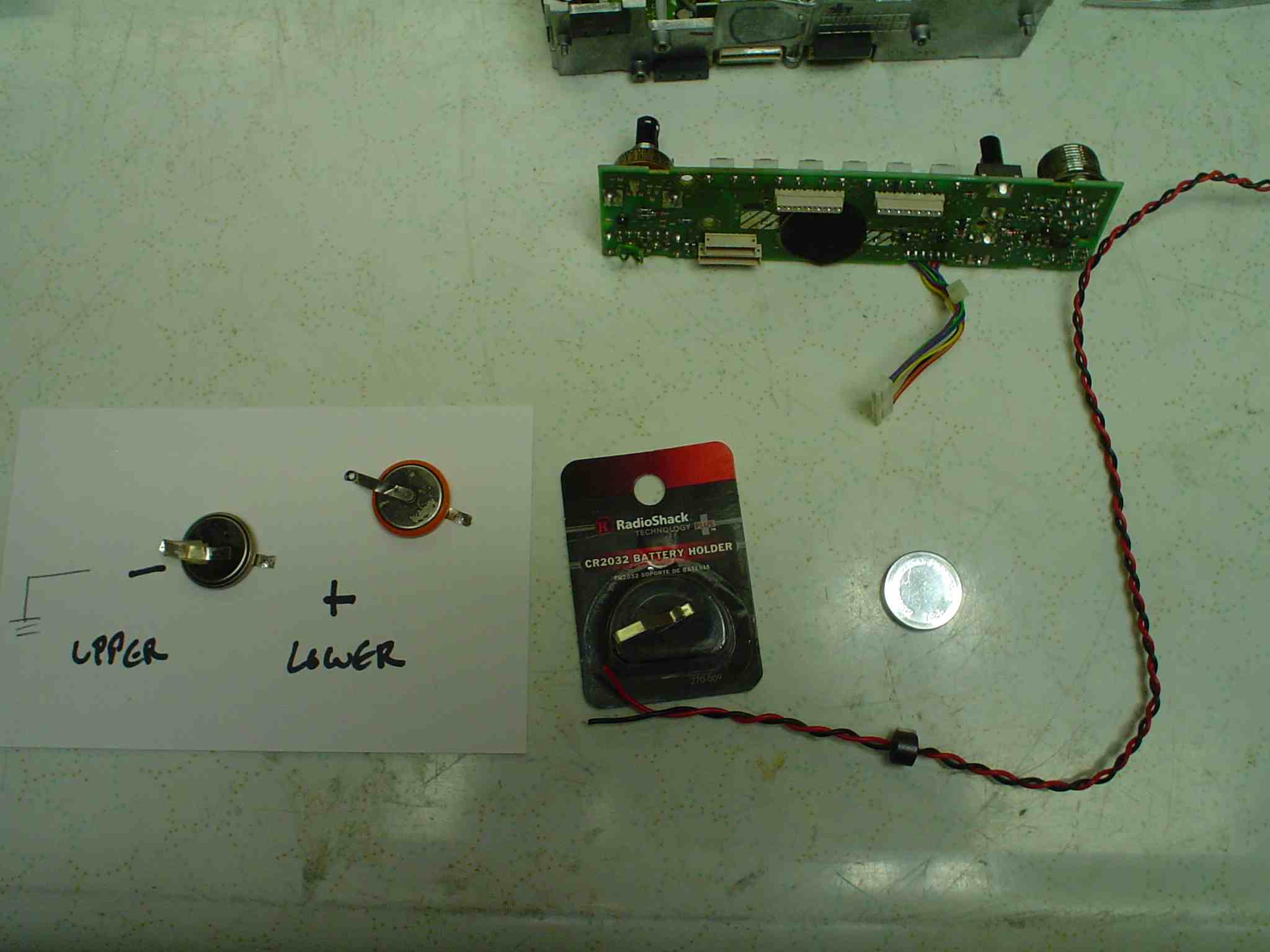
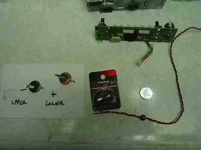
- a battery socket salvaged from a junk computer mother board or Radio Shack #270-009
- a fresh battery type CR2032
- flexible #22 wire
- a ferrite bead
- non conductive glue and insulation to mount the battery holder (or Velcro)
- hand tools
- sufficient test gear to verify proper operation after repair (power meter, scanner to listen with)
- a grounded temperature controlled soldering station 30 watts minimum (to unsolder large tabs on existing battery)
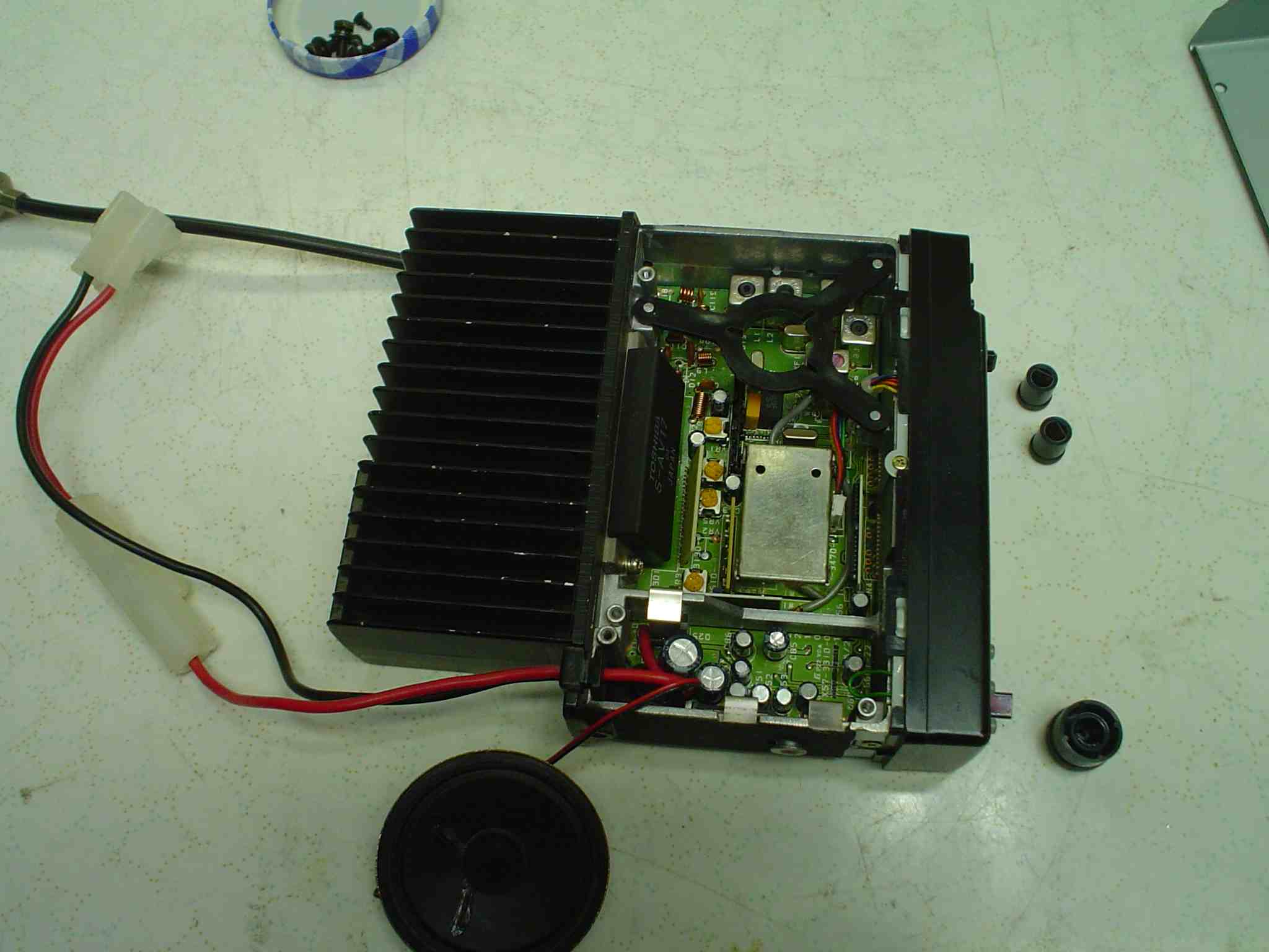
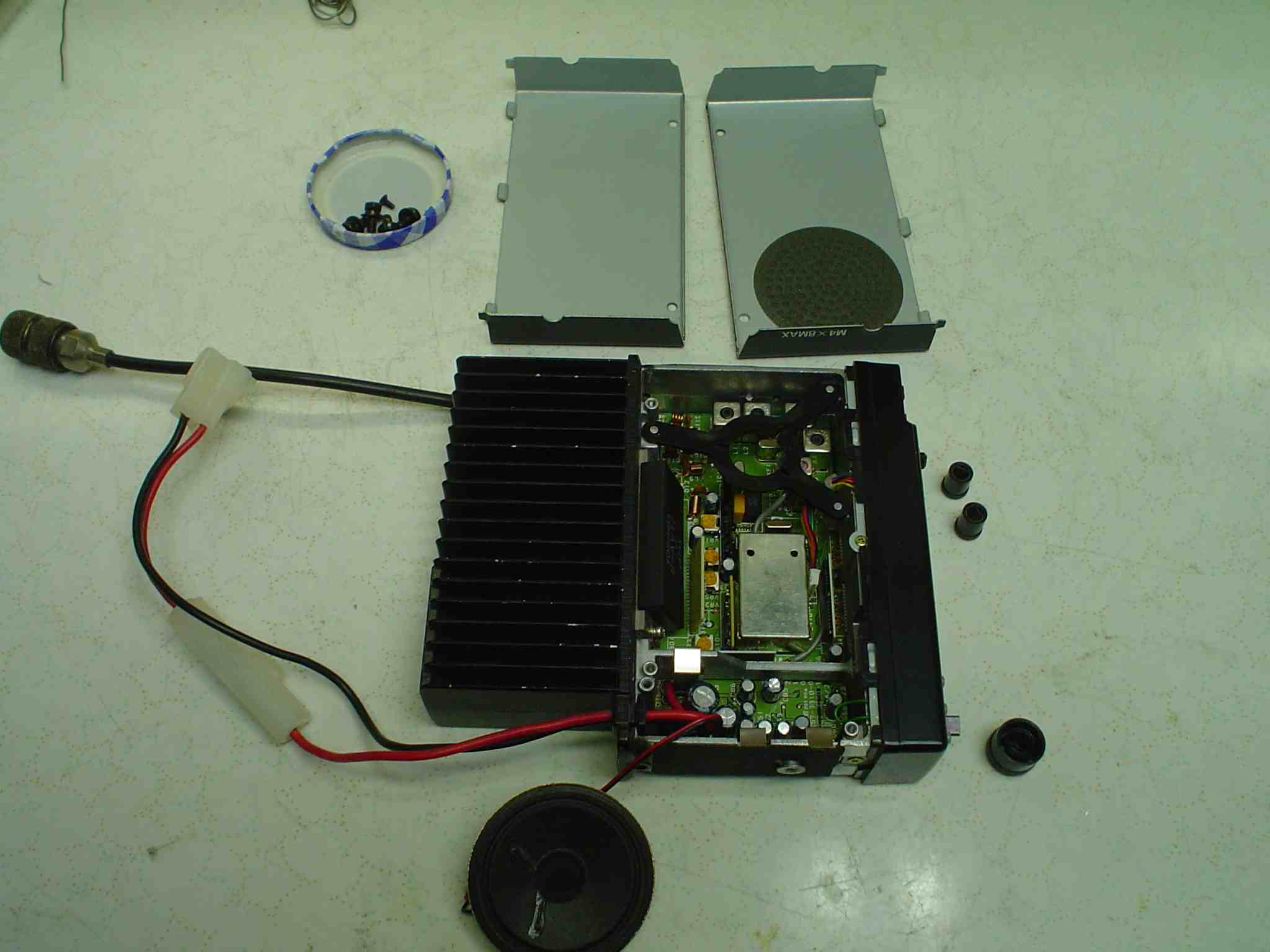
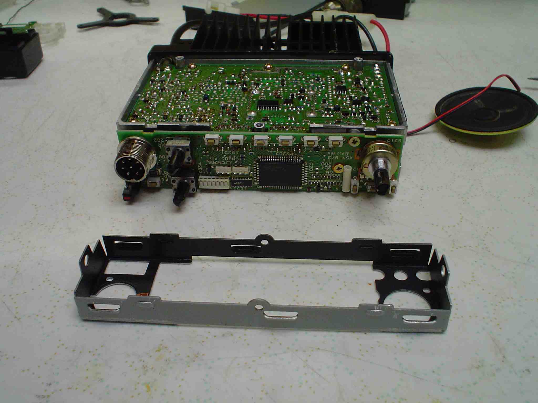
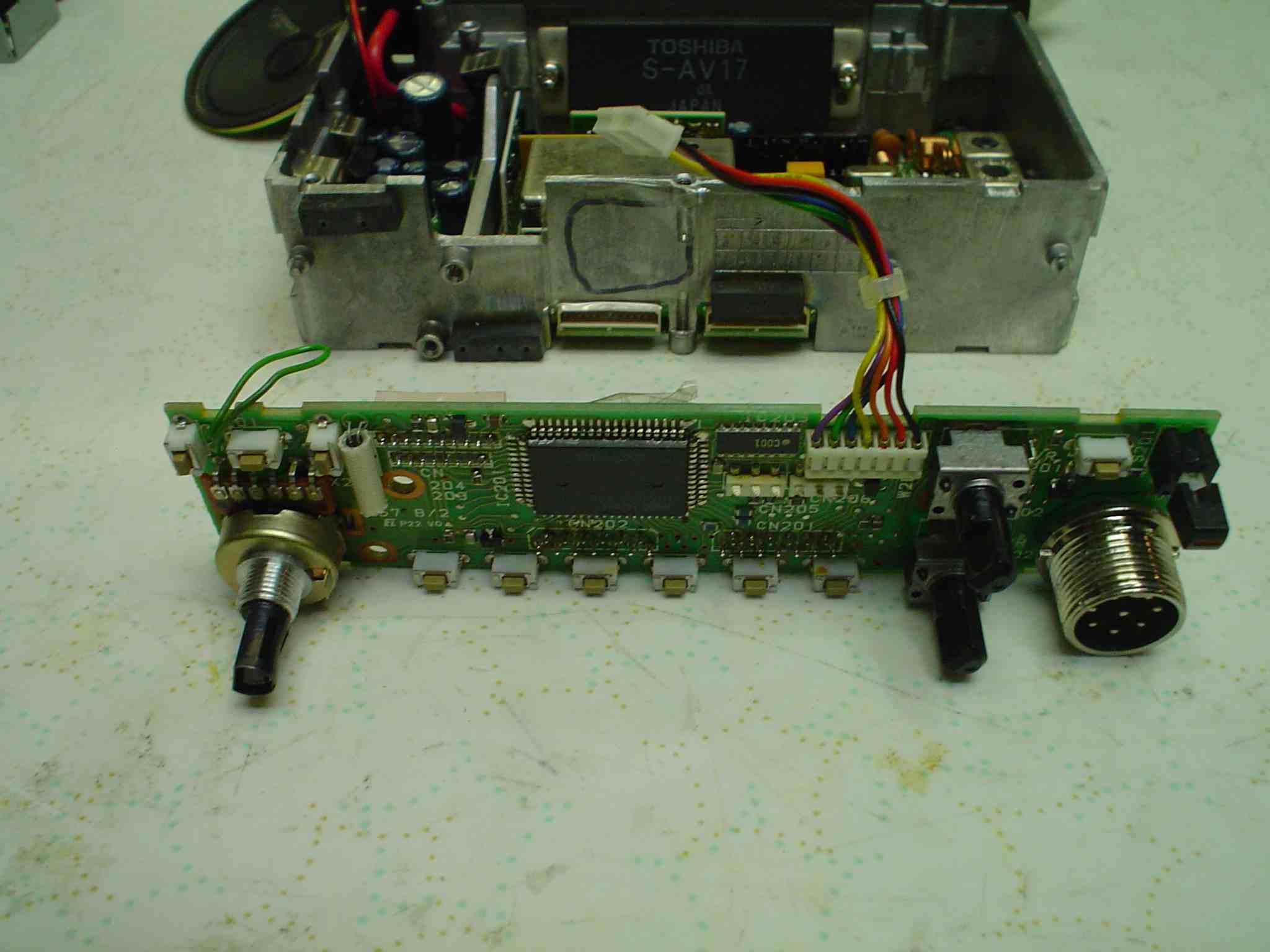
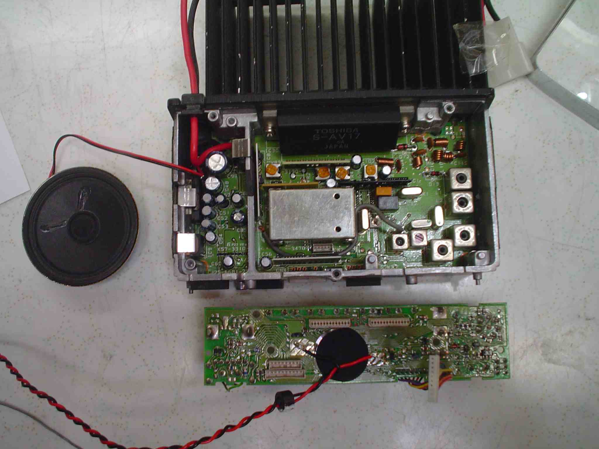
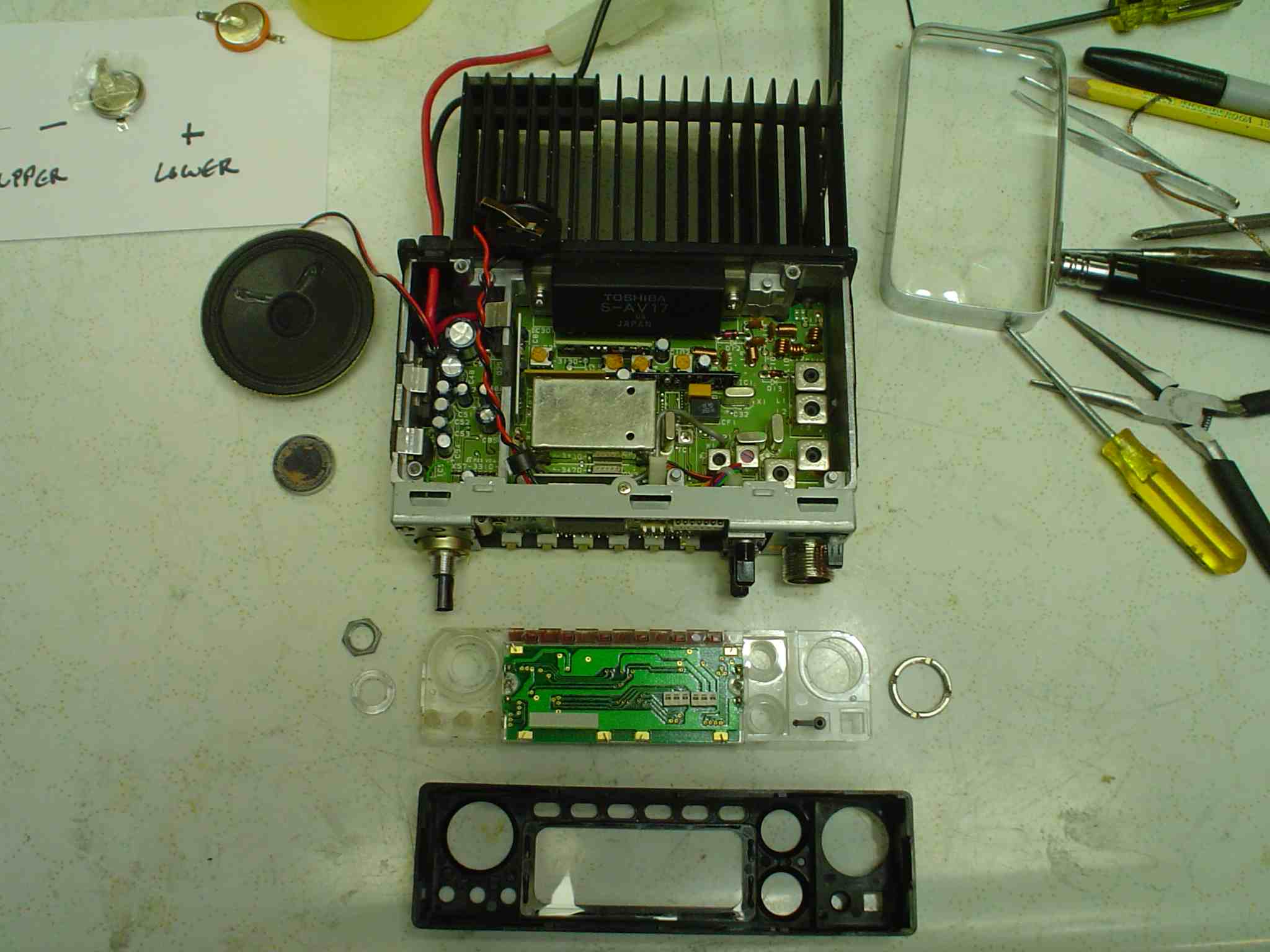
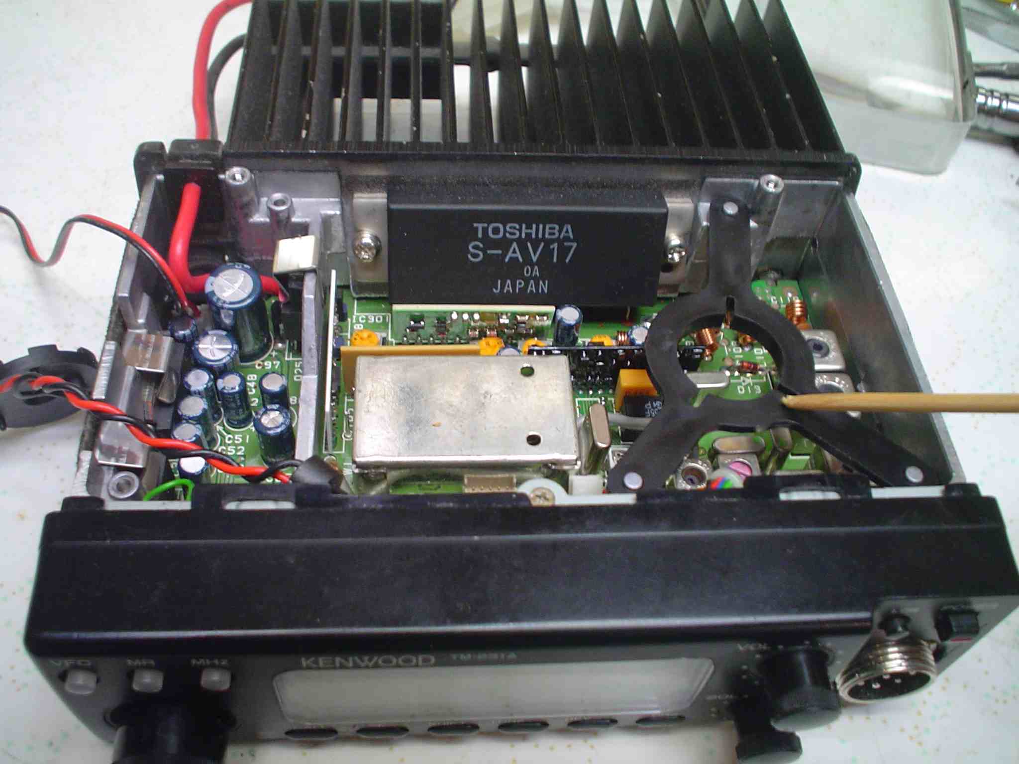
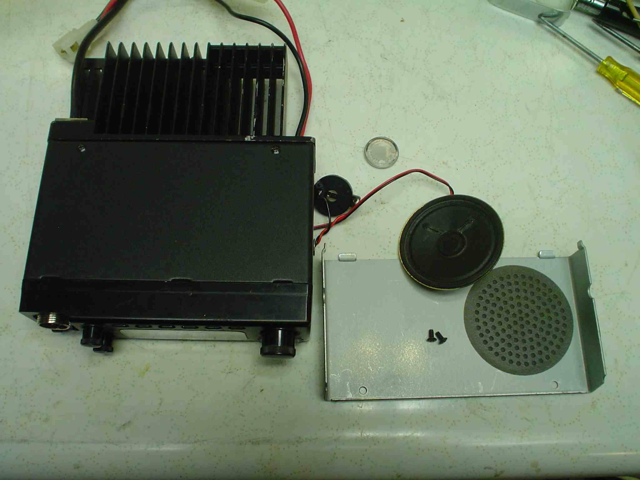
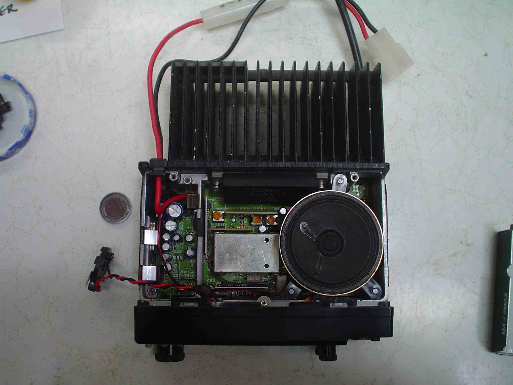
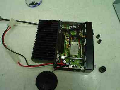
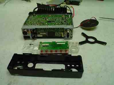
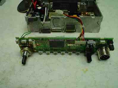
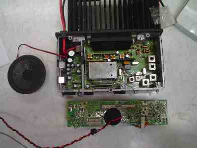
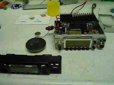
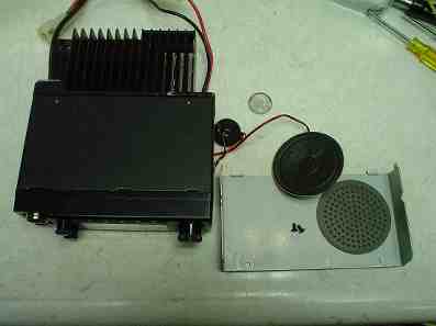
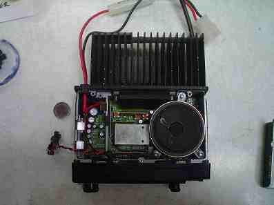
The photo sequence shows how to remove the speaker, front panel, and the front controls.
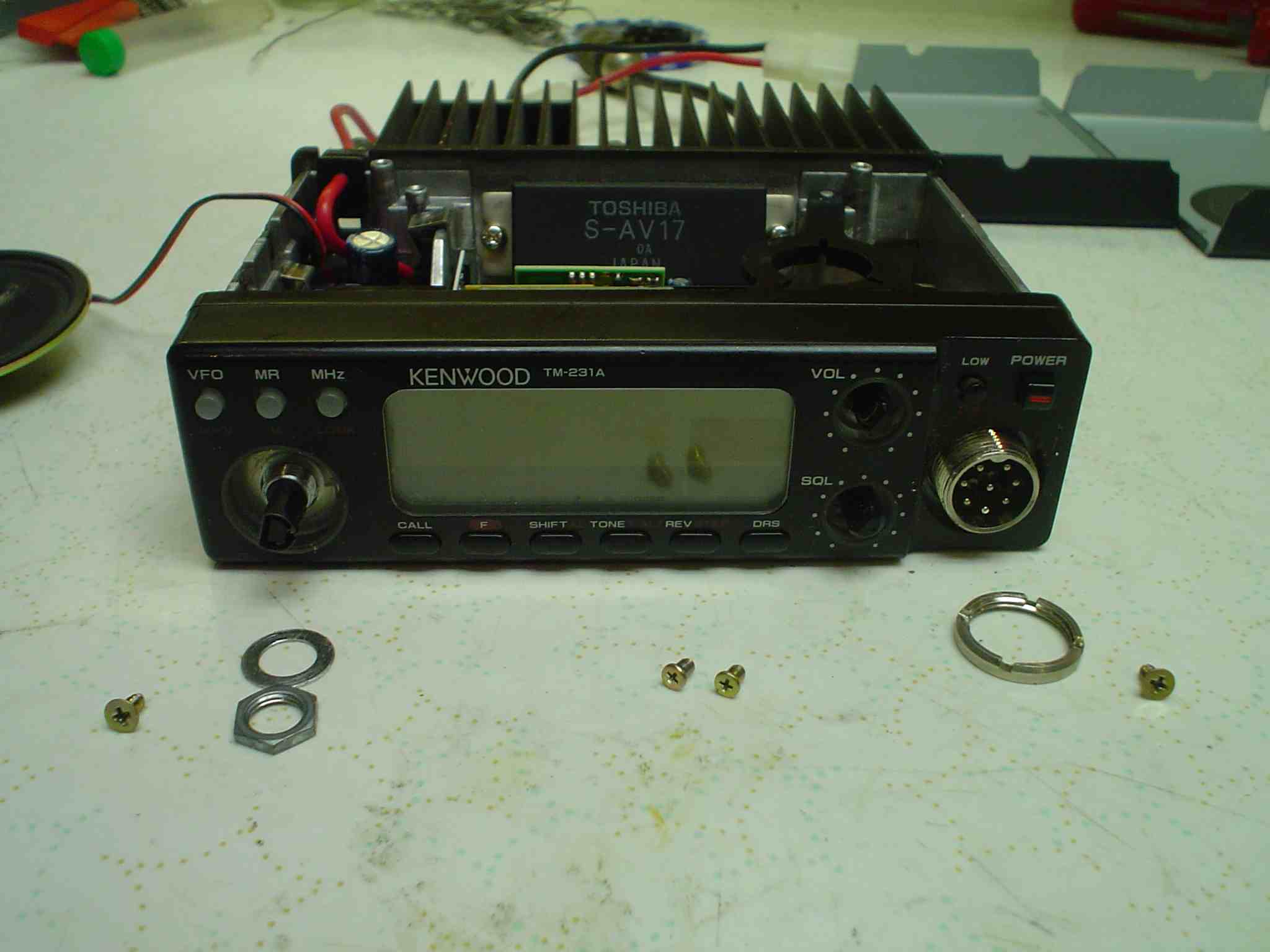
Remove the knobs. Do not use excessive force, and only pull straight out, not at an angle.
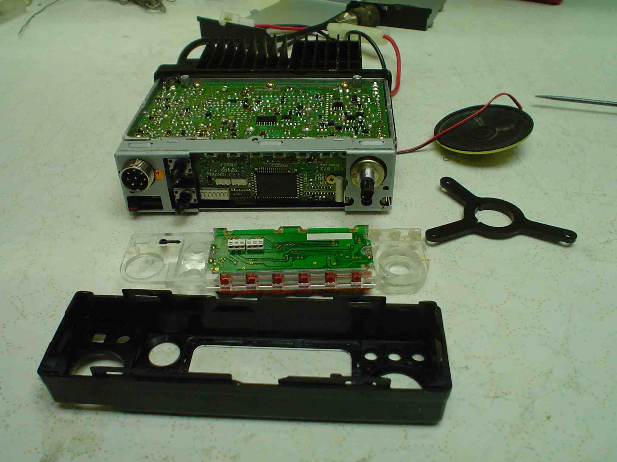
Carefully pry up on the tabs holding the front panel and move it forward.
Remove the flat head screws shown holding the interior plastic panel.
Remove the nuts on the mike connector and volume control.
Do not lose the push button actuators, since they will fall out of the plastic inner panel if tipped wrong.
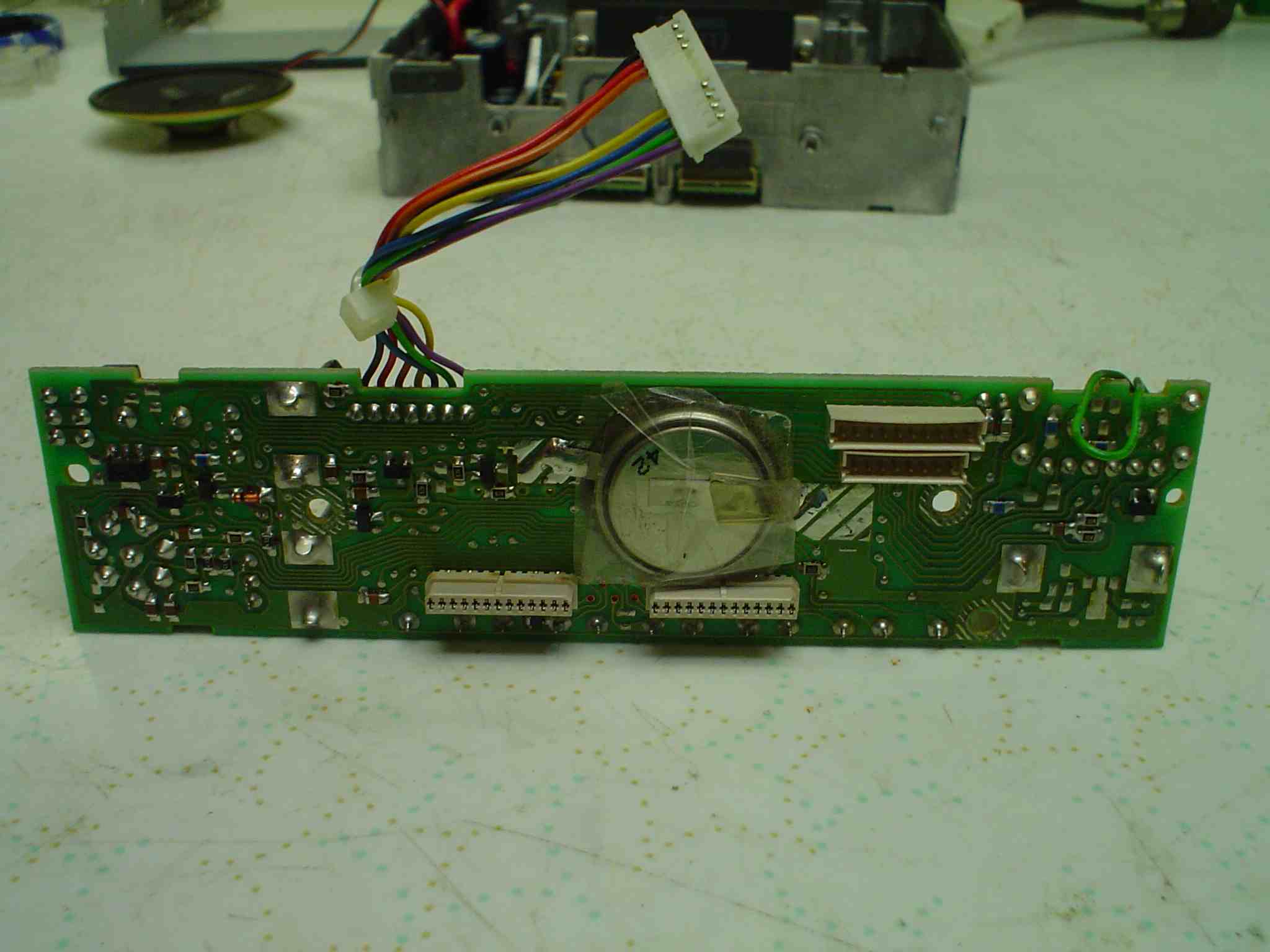
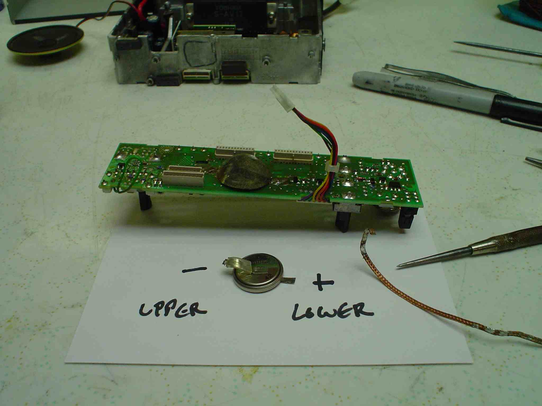
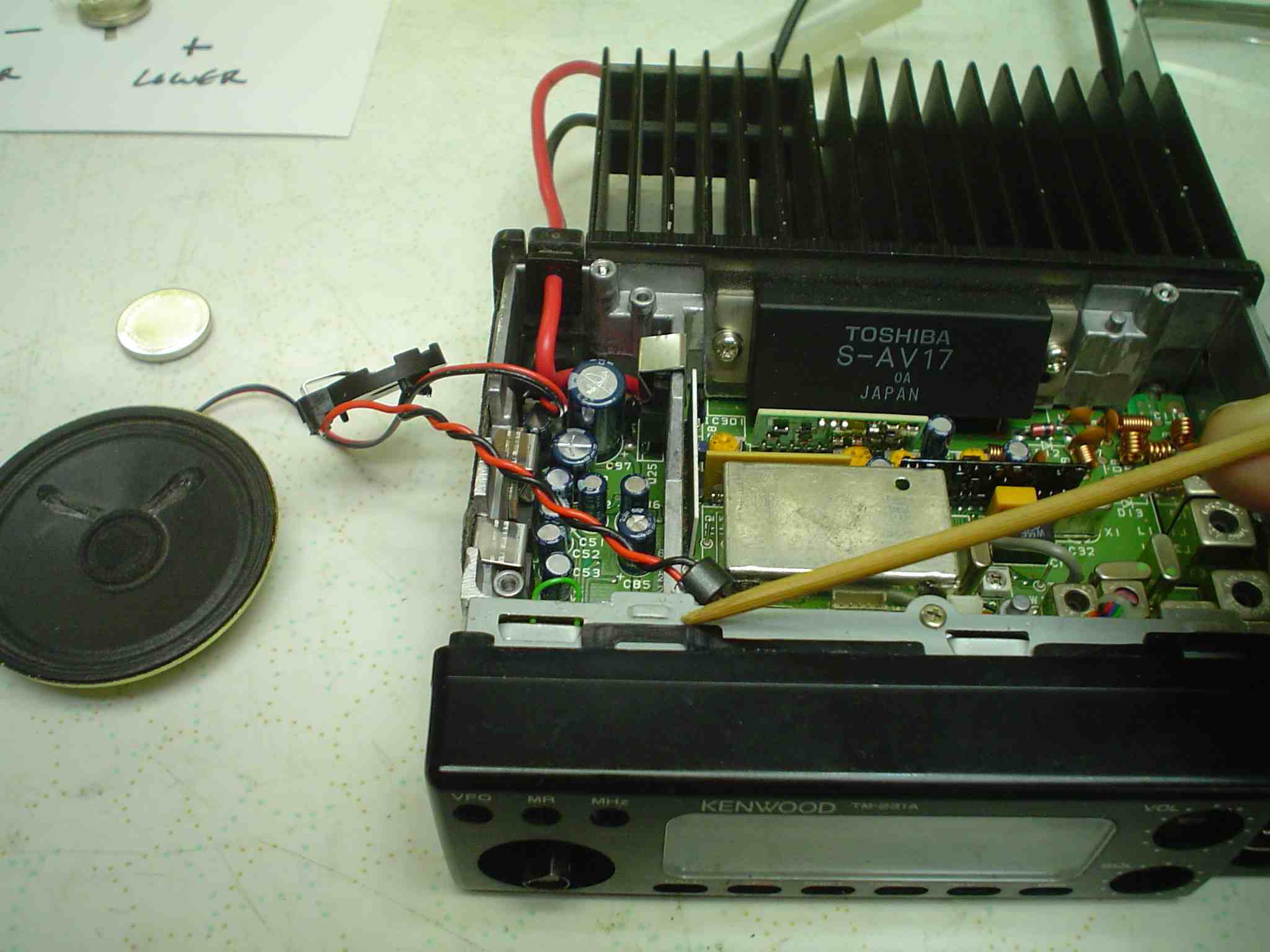
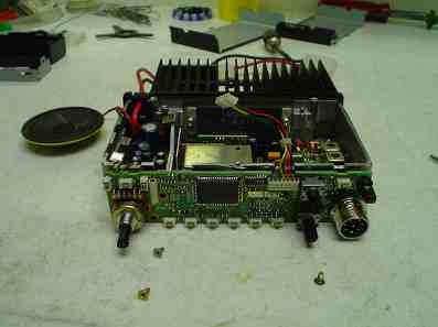
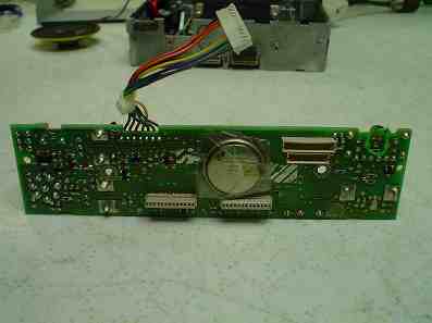
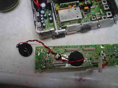
Remove the old battery, being careful to not short it to anything while removing it.
IMPORTANT:
Use of a soldering station with inadequate wattage will cause damage to the ground and power buss on the PC board. Smaller is better only when working on surface mount devices and small parts. Excessive time or excessive heat will damage a board. Get in there, do the job, and get out. Use the right tool for the job. My old Weller WTCPN has enough power to work on tube gear or surface mount, when fitted with the right size and temperature tip. Well, OK, I do have a 5 pound 200 watt behemoth for soldering the tabs on a multi section condenser to the steel chassis in tube radios.
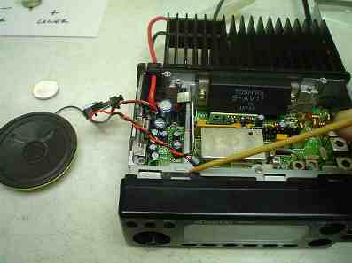
Install the new battery holder and wires sufficiently long to allow you to mount it under the top cover.
Clean up the excess flux when you are done with the board.
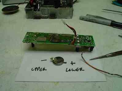
MAKE SURE YOU HAVE THE RIGHT POLARITY ON THE NEW BATTERY HOLDER!
Reassemble the radio.
Route all the wiring to prevent pinching it when the radio is reassembled.
The speaker wires should go along the front panel side to prevent interaction with the RF circuitry.
Secure the battery holder to the square shield compartment on the mother board or somewhere you think it will be safe. DO NOT ALLOW THE WIRING OF THE BATTERY TO TOUCH ANYTHING!
Only after you have tested the radio for operation should you install the battery and check the memory function. Install battery with the 12 volt power off.
OBSERVE POLARITY WHEN INSERTING BATTERY!
Here are the pictures of the process.
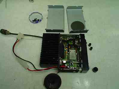
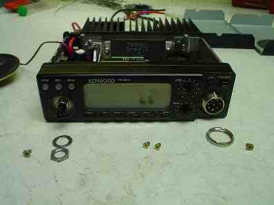


|